Replacing your factory ECU with an aftermarket unit like LINK, Haltech, Motec or any other aftermarket ECU opens a world of opportunity for modification. Adding sensors for engine protection or Flex fuel, converting to Sequential fuel injection or Sequential spark. Wasted spark was common in the nineties, many vehicles used it. So, what is it and how does it compare to sequential spark.
The chain of events, the what and how of a getting a car on the dyno.
A clean 1990 E30 BMW in for a tune. Engine rebuilt with a set of 268 Clive cams, Forged pistons, rods and ITBs. The engine was running very poorly with soot out the tail pipe. Fact is it was only running on 4 or 5 or the six cylinders.
This car was put together nicely. Had fruit from Hillside, racing hardware developments carbon fibre inlet, Quick rack, fresh suspension arms and coil overs, new extractors and full exhaust and a Haltech Sprint 500 ECU in piggyback. An old ECU for sure. The plan was getting the car running correctly and iron out any bugs prior to upgrading the ECU and stepping up to a PDM or two.
The different names are confusing. More so due to the legacy terms of mayor and minor service. All these terms in the automotive industry are used to describe different levels of maintenance or servicing for a vehicle. The specific tasks included in each type of service can vary between manufacturers and service providers, but generally, the following distinctions are observed:
Minor and major service stem from the time, vehicles required spark plugs and points to be changed every second or third service. The minor service included tasks like:
Oil and oil filter change.
Visual inspection of the vehicle components.
Check and top-up of fluid levels (coolant, brake fluid, power steering fluid, etc.).
Inspection of lights, wipers, and other basic components.
Tyre pressure check and adjustment.
Basic safety checks.
Often talked about, but what is Injector latency. Latency or dead time is the time delay between the initiation of a process and the occurrence of its first noticeable effect. It is the time delay from commanded to open or close to the event occurring. In the case of fuel injectors this is described in milliseconds. Fuel pressure, voltage, injector design and even fuel temperature will change the dead time.
Here's how the process typically works:
1. Electrical Signal: The engine control unit (ECU) sends an electrical signal to the fuel injector when it's time to inject fuel into the combustion chamber.
2. Injector Response: Upon receiving the signal, the fuel injector needs some time to physically open and start delivering fuel. This delay is known as opening injector latency.
3. Fuel Injection: Once the injector is open, fuel is sprayed into the combustion chamber in a controlled manner, mixing with the incoming air for combustion.
4. Injector closing response: Electrical signal ceases being sent from the ECU when the injector is programmed to close. Injector again requires time to react to the change in electrical signal. This is closing latency.
Add opening and closing latency and you have the total dead time.
Our friends at Haltech made the diagram below to visually explain what is happening.
Blue = Commanded pulse time
Yellow = Time to energise solenoid before the injector starts to open.
Red = Opening time of the injector
Orange = Closing time of the injector
You can see that the commanded amount of fuel (blue) that was injected is a smaller amount than the pulse time. We wanted fuel to be injected from the start pulse to the end pulse. What we got was visibly less.
Now, keep in mind that the Yellow, Red, and Orange sections remain the same size, no matter what the commanded pulse time is. If we halved the commanded time, we would then find that most of the time the injector is not actually open. This is why the impact of dead time is larger at idle and low speed (when small injector openings are used) and minimal affect at high speed and high load conditions.
To correct for the loss of fuel we turn the Red triangle and the Orange triangle into rectangles constructed of the same area. Add the red rectangle to the end of the pulse, and then subtract the Orange rectangle from it. We subtract the orange rectangle because this was additional fuel we received while the injector was closing and not fuel lost like in the Red section.
Now we add to the tail end the missing Yellow section which is the time to energise solenoid before the injector starts to open.
Red = Injector open time MINUS injector close time
Orange = Time to energise solenoid before the injector starts to open
We now have one large purple section of missing injector pulse time.
If we now measure the amount of time between the Old End Pulse and the New End Pulse, that is the amount of additional injector opening timing time that is needed to get the correct amount of fuel delivered to the engine at a given voltage and fuel pressure.
An example of a dead time table showing voltage and fuel pressure is below.
Entering the incorrect dead time valves either to large or to small with have a visible impact on the VE table.
This is how the VE table should look if the injector data is correct.
Dead Time Too Low
When the dead time is set too low, we need to over-compensate in the light load areas by increasing the VE numbers to get more fuel. This shows in the VE table that something is not set correctly. We must increase the dead time to bring the VE numbers back to normal. Very large VE numbers are used to correct the AFR at low-speed, low load area.
Dead Time Too High
Conversely, if the dead time is set far too high we can create situations where the VE can even reach ZERO as we try to tune the car. Obviously, the VE cannot be zero as some air is passing through the engine, we know that this is not correct and the dead time needs to be decreased.
How To Set the Dead Time If The Data Is Not Available
If no data is available, google often is your friend to find flow rate or flow rate can be measured on a flow machine.
As a general rule
With engine idle vacuum of -60kpa a VE value of around 50 is expected.
Dial in the dead time values to achieve the expected lambda value for the given engine combination. Large overlap camshaft will change the idle vacuum and lambda value targets.
Approximating both the Flow Rate and dead time.
After taking an educated guess at the flow rate and dead time so that the engine is running and idling without having touched the VE base table or using the general rule, the next step is to get a little closer to the flow rate. To do this we need to bring the engine load and rpm up to a level where the dead time has less effect, and the flow rate has a significant effect. We pretty much need the engine at full load and keep the rpm above idle but low enough that the engine is not being beaten on too hard. Aim for around 1500 to 2500 rpm for this. While under load if the Lambda is trending lean, then you need to adjust the flow rate down. If you are too rich you need to adjust the flow rate up. You need a dyno to do this.
Approximating the Dead Time
After the flow rate has been adjusted, now when you come back to idle the lambda will have changed. Now adjust the whole table up or down to bring the lambda back to your Target. After this is complete go back and retest the flow rate again, then repeat the dead time adjustment one more time.
After you have the dead time worked out, the next step is to vary the voltage. The easiest way is to disable the Alternator and allow the voltage to drop. Typically, the engine will be at around 14V with the alternator running and without it, you can let the voltage drop down to 12V. This will give you 2x point from which to take a good solid guess at the curve. In reality, if you are at 10V and still driving you probably have far bigger concerns than your fuelling being off by a couple of percent, and as such messing about with small changes from here is usually counterproductive. If it is of concern for you, then you need to find a way to let your engine run at lower voltages.
And that is dead times.
A project car is a vehicle being modified or restored. Sounds simple.
This means the car is often not driveable. The engine may or may not run. A lot of work is required to complete the car.
Adding to the challenge is a project purchased unfinished and or multiply people have been involved on the various aspects of the build.
In the world of performance engine tuning, achieving optimal airflow is crucial for maximizing power output. When it comes to cylinder head porting, two primary methods stand out: CNC (Computer Numerical Control) porting and traditional hand porting. Both techniques aim to enhance airflow and optimize combustion efficiency, but they differ significantly in their approach and outcomes. Let’s explore the advantages and drawbacks of CNC porting and hand porting, helping you make an informed decision for your specific needs.
The purpose of the tyre pressure monitoring system is simple, notify when a tyre has low pressure. TPMS have become common place since mandated by the United States in 2007. Two different methods of tyre pressure monitoring are in use, Direct and indirect. Lets have a look at the system operation.
VSB14, vehicle standards bulletin 14 or the NCOP (National code of practice) is the document referred to when performing vehicle modifications. VSB14 is broken down into a number of sections. Each section dealing with a major element of the vehicle.
Sub section 1 of whichever section of VSB14 you are reading includes the scope, basic modifications not requiring certification, modifications requiring certification and in some cases modifications not covered.
In section LS (suspension) some of the basic modifications listed are changing shocks, springs and sway bars or adding a strut brace. Even with the listed basic modifications there are conditions and limitations. A condition is set for the amount of ride height change that can be performed without certification. Then within the certification section a maximum and minimum ride height is specified. Adding to the complexity within the certification section is the checklist of the mandatory items required.
As an example of recommend vs mandatory, table LA1 Recommended maximum engine capacity provides a method of calculating the recommend maximum engine capacity. As noted in the table title, this is a recommendation.
Different names for the same part. Power Distribution Module or Power Distribution Unit. Manufactures are using advanced electrical systems to power various components, from lights and infotainment systems to safety features and engine control modules. To efficiently manage and distribute power throughout the vehicle, power distribution modules (PDMs) play a crucial role.
All the well-known aftermarket ECU manufactures are also making PDMs. Motec, Link, Haltech and ECU master to just name a few. Let’s have a look into the world of PDMs, exploring their functionality, benefits, and provide a very basic install procedure.
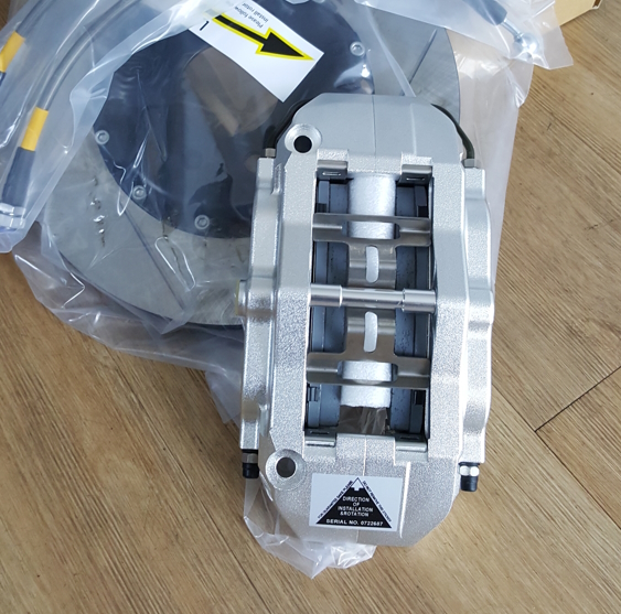
While there are several types of brake callipers available, two common configurations are radial mount and axial mount brake callipers. These calliper designs differ in their installation method, construction, and overall performance characteristics. Let’s delve into the details of radial mount and axial mount brake callipers, highlighting their unique features, benefits, and applications.
Search the title of this blog and you will get a lot of answers. All the following information is correct at December 2022. The information applies to Queensland registered vehicles. Wait, why only Queensland? I am going to try to keep this simple. The truth, this is messy.
Sure you could throw a set of spark plugs at it and see what happens. Might as well throw a set of coils in there at the same time. What if that does not fix it. In reality the only approach should be to test and inspect. Let’s take a look at how we go about this. This is a fairly generic approach that can be applied to many spark ignition engines.
Two reasons come to mind, to get that look and to retain heat energy in the exhaust manifold.
Something you may expect to be a straight forward and even boring is an area where a small mistake has a large impact. Performance and reliability is compromised when a poor selection is made. Everyone’s favourite topics will get a mention. Fuel choice, operating pressure, temperature, flexibility, durability and cost.
Diesel particular filters or DPFs have become the solution of choice for many manufacturers to deal with soot and ash when diesel is burnt. Basically they are a filter in the exhaust that collects soot and stores it to be processed during a DPF burn.
We are all about performance and we all know that any restriction will reduce the performance of an engine. So what can we do about the DPF? What is it and how to look after it?
The DPF can be deleted from the exhaust and the software. This is the simple solution to all the issues caused by having a DPF. I am not going to go into all the legal stuff of removing an emission related device. I am simply saying that is the simple solution.
Why tune.
The reasons to tune any engine diesel or petrol are exactly the same. You want the engine to be more efficient and or recalibrated to suit the modifications you have made. You may want better fuel consumption and torque for towing. You may have made modifications. A larger exhaust better intercooler or as advanced as a replacement turbo and injectors
If you want to get the best out of your car then there are some easy modifications that you can make to increase the power that you get from it. Here we explore 7 simple things you can do today to maximise the performance of your car.
When buying a performance car it is vital to get it right because you’ll be making a very significant investment. We all know horror stories about getting it wrong by buying a lemon and this is far more serious when you’re buying a performance car because of the level of investment you’re making. Here we explore the key checklist you should follow in buying your performance car.
Let me guess – if you're reading this, we'll bet you'd like to know how to make your car accelerate faster? How about handling and gripping the road a little better? Or maybe just braking more efficiently? Yeah - we thought that might get your attention.
Just for you, we’ve compiled a list of the top eight ways to boost your car’s performance, sourced directly from industry experts around Australia.
Do you have a suspicion that you could get more out of your car? If you're keen to boost its performance, but don't know how to make it happen, here are some tips to get you started — straight from the mouths of successful car owners.
If you like a car that makes every drive feel like an adventure, you can't go past a performance vehicle. However, if you own a performance vehicle it's important to watch your car costs as they can easily become overly expensive if you don't take care.
Here are seven tips to make sure your performance vehicle doesn't end up costing you big bucks.
Many of us have seen and heard a Dyno power run. The power runs are part of tuning but a lot has to happen to get to the power runs. Large numbers of vehicles are presented for Dyno tuning with faults. Many of these faults may not even be noticeable during normal driving. By design the dyno places high loads often at high speeds on the vehicle. This and the data logging capabilities reveal unknown faults that will prevent tuning from being performed and need to be rectified. The issues may not necessarily be engine related either. We are going to run over some of the common issues we see during our dyno precheck or are discovered during the dyno tune. We are going to focus on 3 things, Fuel system, Ignition system and Engine.
A narrowband O2 (Oxygen) sensor only reads either rich or lean of Stoichiometric. Stoich is the ration to completely combust the fuel. So a narrowband will only read rich or lean. It does not tell you how far away you are from Stoich.
A wideband O2 is designed to read a board range of air fuel ratios. Some widebands will read from 10:1 up to 20:1. Knowing how far we are away from Stoich we are able to calibrate an engine under all conditions. Especially the areas of full power which are critical to performance and longevity.
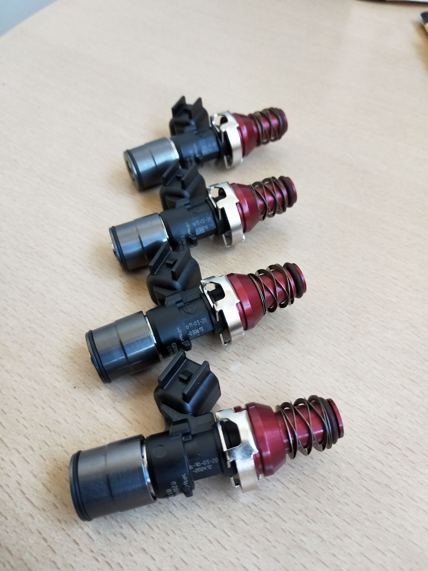
Top feed fuel injectors are by far the most common, engines like the 4G63 use top feed injectors. Some of our favourite performance engines like early SR20, 3SGTE, 1JZGTE, RB25DET and EJ20 all come standard with side feed injectors.
So what is the difference?
Side feed injectors:
For side feed injectors the fuel enters through slots machined into the sides of the injector. The fuel rail is combined into the inlet manifold or cylinder head.
Top feed injectors:
As the name suggest fuel feeds into the injector from the top.
Why change to top feed?
Side feed injectors are size limited. 1000cc is about the largest size available.
The flow rate of the integral fuel rail is limited.
Side feed are expensive compared to top feed.
Most performance inlet manifolds are made to suit top feed.
Top feed advantages
Cost advantage when changing to larger injectors.
Fuel pressure is generally more stable in a top feed fuel rail.
Top feed fuel rails usually flow more.
Top feed is simply more common.
Can use very large injectors 2000cc
Top feed disadvantages
A conversation kit is required. Which may also require changing plug connectors.
Fuel flow does not cool top feed like it does on side feed.
Side feed advanatages
Some cooling effect offered by the fuel surrounding them.
Side feed disadvantages
Cost.
Limited range.
Restricted by size.
More prone to leaks.
Stock cars are using plastic for just about everything. Not us. Plastic has it place, luckily we have ways to replace that plastic with strong and durable parts. Just look at the gear linkages as an example. They look trick also. Just ask us PH 31235373